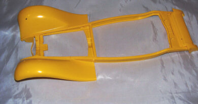
’57 Chevy Strip version-02
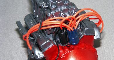
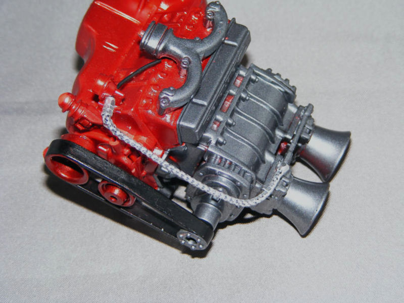
One of the first things I noticed now the supercharger, pulleys were fitted was that the kit’s fuel system was pretty basic—just the fuel rail connecting pipe between the two carburettors, with no real sense of how fuel would actually get there.

To bring the engine bay to life, I decided to scratch-build a more convincing fuel delivery system.
I began by drilling out both the fuel filter and the fuel rail. For the filter, I used a 1.3mm drill bit to go right through, ensuring a clear path for the wire.

The fuel rail intake got a 0.7mm hole, about 1mm deep, to accept the new fuel line. This step is crucial for a snug, realistic fit—don’t rush it, seriously don’t rush it, and always check your drilling alignment .
For the main fuel line, I used a 30mm length of standard 7/0.2 equipment wire (12mm O/D), which is easy to find at electronics stores. This was threaded through the filter, while a 4mm piece of the kit’s original 0.65mm O/D wire was glued into the carburettor with a tiny drop of superglue. The fit should be tight, but not forced, and will become the fixing point for the next stage.
To really sell the look, I raided my spares box for a length of braided cable—about 90mm long. If you don’t have braided line, flexible tubing works too, but the braid adds a touch of realism that’s hard to beat. I glued one end to the fuel filter, then slipped on a couple of scale hose connections (aftermarket or scratch-built), and glued the other end to the carburettor. A dab of superglue at each end locks everything in place. The remaining wire from the filter will later connect to the bulkhead’s fuel feed, completing the circuit.
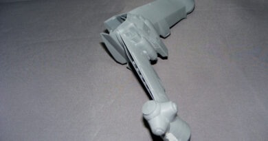
With the fuel lines sorted, I turned my attention to the throttle mechanism. This is an area where a little extra effort pays off in realism and visual interest.
I started by digging out some photo-etched brackets from my spares. Each bracket had two 1mm holes—perfect for throttle levers. If you don’t have photo-etched parts, you can fabricate levers from thin plastic or brass rod. I glued a lever to each carburettor housing with superglue, making sure they were aligned for smooth operation.
Using 1mm diameter plastic rod, I cut a 21mm length and bent the ends at 90 degrees to fit into the levers. This rod acts as the linkage between the two carburettors, ensuring they open and close together. Test-fit before gluing to ensure free movement.
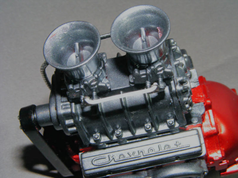
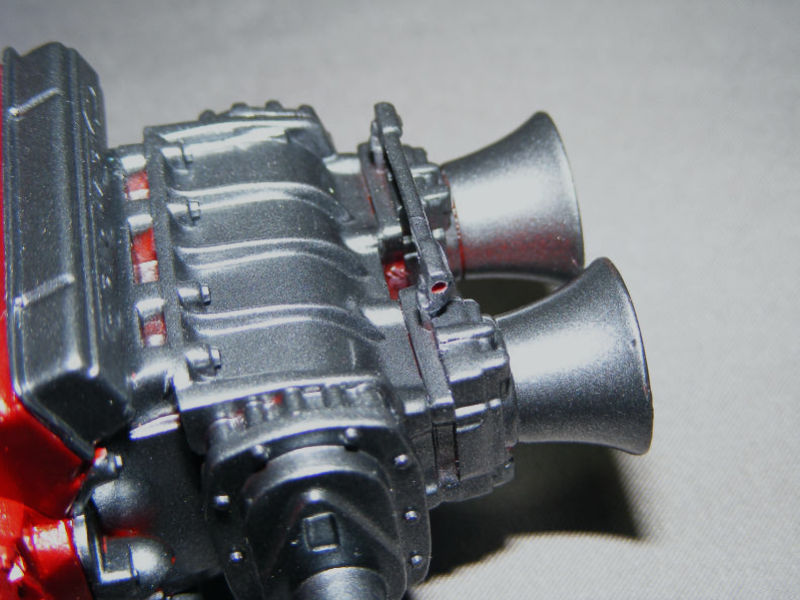
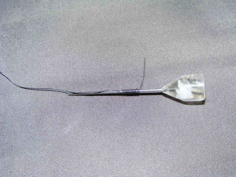
For the return spring, I used 0.25mm fixing wire, winding it around an old glue nozzle for about 20 turns.
Leave 2mm unwound at each end for mounting. I drilled a 0.3mm hole 1–2mm deep in the front carburettor to anchor one end of the spring, with the other end resting on the throttle link bar. A tiny drop of superglue secures it.
The throttle cable itself was made from a 60mm piece of 7/0.2 gauge wire, with about 5mm of insulation stripped off and the wire wound to simulate the cable. I used a photo-etched bracket to hold it in place, but you could also use a small piece of bent brass or plastic. The cable was routed to look as if it would connect to the firewall or pedal assembly in a real car.
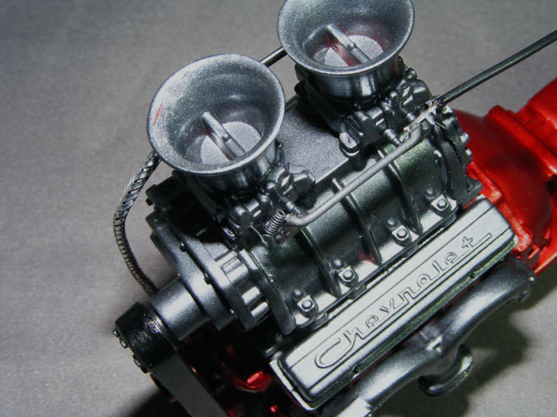
Even without aftermarket parts, this scratch-built assembly adds a ton of character and mechanical realism to the engine bay.