’57 Chevy Strip version-03
Ignition wiring is one of those details that separates a good engine bay from a great one. I wanted mine to stand out, so I went all-in to change a lot from the original .
Earlier I had to take the distributor out from the engine block, but in this kit I could use the distributer meant for the stock engine and painted it along with the ignition coil.
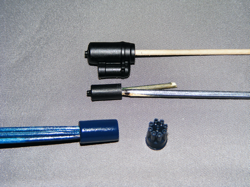
Using a 0.7mm drill, I made nine holes in the top of the distributor cap, one for each plug wire and wire from the ignition coil. also the centre hole in the ignition coil. I also cut off the point where the two side wires would fit on the ignition coil & drilled them as well.
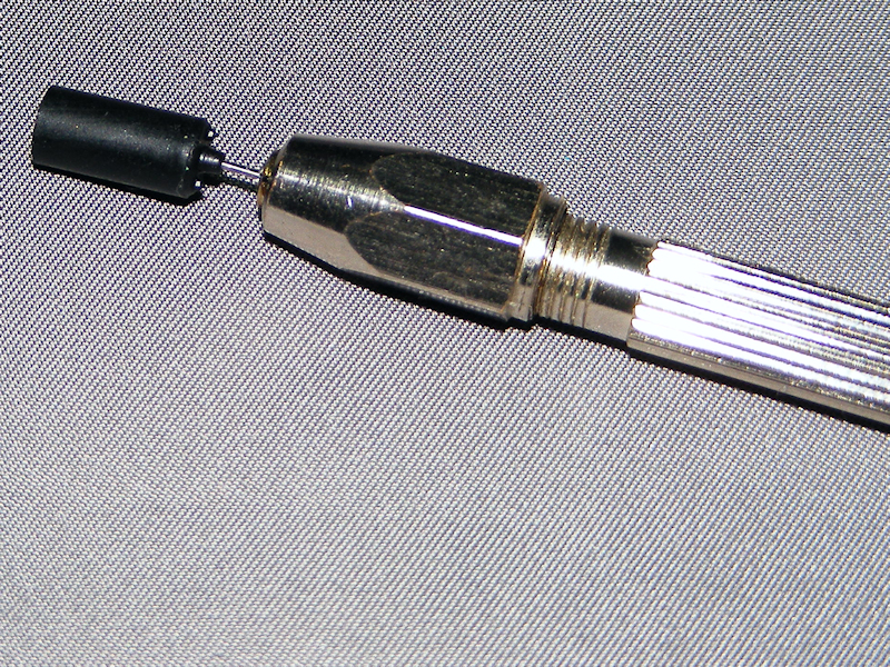
The kit-supplied wire was too thin for my taste, and I wanted them to be red to match the engine, so I used 7/0.2 gauge electrical wire. I cut each wire about 2–3cm longer than the kit’s guide suggested, to allow for natural bends and routing. To create scale plug boots, I stripped 3mm of insulation from one end, then gently pulled the outer coating off with pliers and my fingers. Yes, it was a tedious but rewarding process. This gave me tubing with a 12mm O/D, perfect for scale.
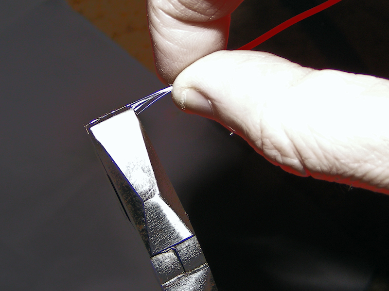
I cut 20mm pieces of 0.65mm O/D plug wire (1/24 scale) and pushed them into the tubing to allow them to fit into the drilled distributor cap. No glue was needed as they fitted snugly inside.
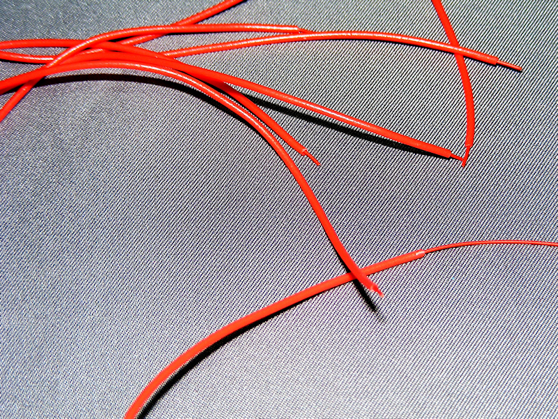
I then dipped each end into some superglue & into the holes in the distributer.
After allowing time for the superglue to set, the ignition coil and wired distributor were glued in place. I didn’t position any of the wires so this would allow the parts to set without any tension or movement.
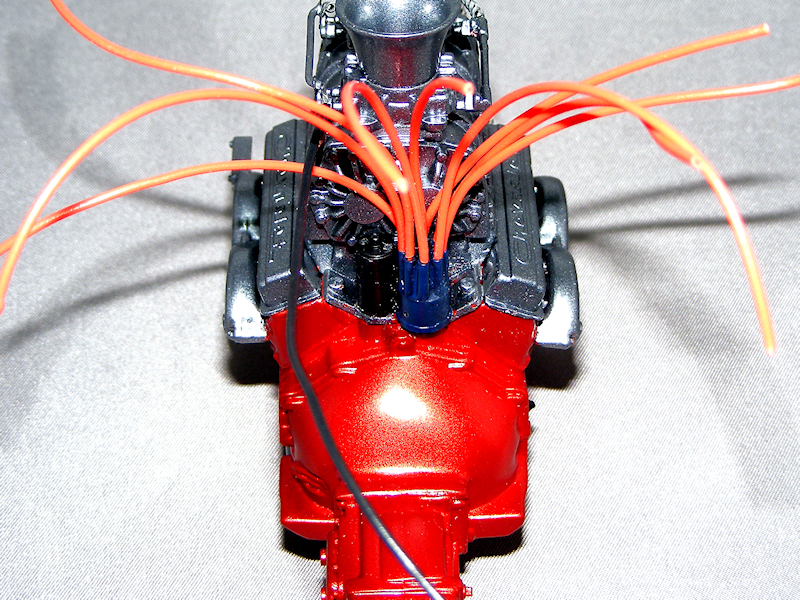
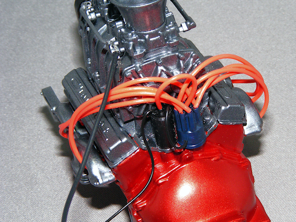
Once cured I followed the wiring guide & just pushed the ignition wires into the holes in the engine block & the centre hole in the ignition coil. I could have fitted spark plugs into the engine then connected the wires to them, but I do not have any to hand.
Using the black wire that came in the kit I cut a 25mm piece which goes from one of the side holes in the coil to the bottom of the distributer. A longer piece of the black wire around 70mm goes into the other hole in the coil & is left to be cut to length later. This will later be fitted into the bulkhead. I then dipped this end into some superglue & into the holes in the distributor.
Allowing sometime for the wires to fix, it is time to follow the wiring guide & just push the ignition wires into the holes in the engine block & the centre hole in the ignition coil. I could have fitted spark plugs into the engine then connected the wires to them, but I do not have any to hand.
Using the black wire that came in the kit I cut a 25mm piece which goes from one of the side holes in the coil to the bottom of the distributer. A longer piece of the black wire around 70mm goes into the other hole in the coil & is left to be cut to length later. This will later be fitted into the bulkhead.
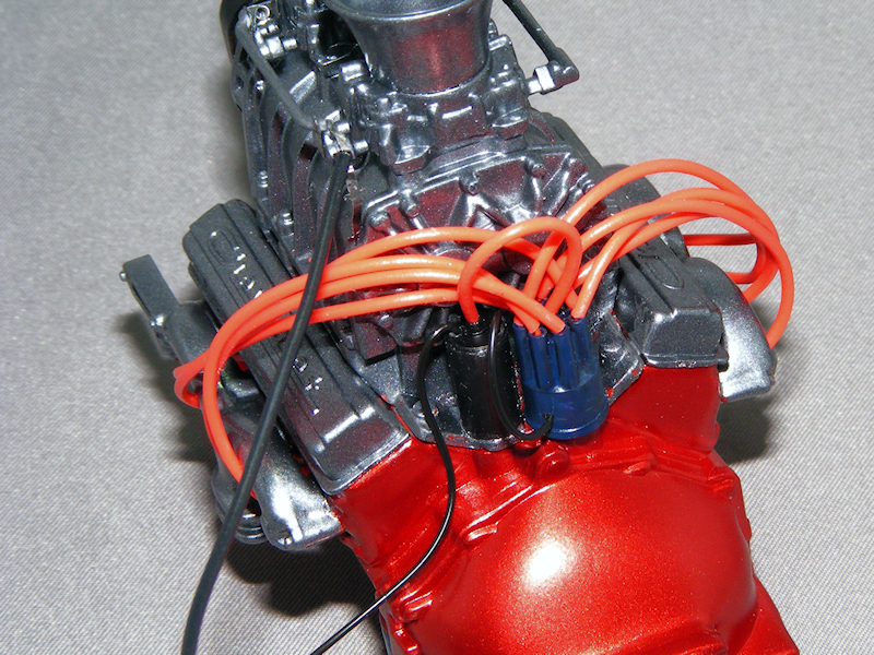
Visual Impact:
I chose red for the ignition wires to match the overall theme and add a pop of color to the engine bay. The result is a highly detailed, visually striking ignition system that really elevates the build.
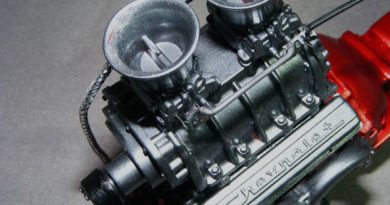
The starter motor was next. I painted the main body in a metallic shade to represent the cast housing, and picked out the end cap and mounting flange in a slightly different tone for contrast. Once dry, I glued the starter to its mounting point on the engine block, making sure it lined up with the flywheel and wouldn’t interfere with any other components.
To add an extra layer of authenticity, I decided to replicate the earthing strap that connects the starter motor to the engine block. I took some of the fine strands left over from making the ignition wires and twisted about 25 of them together to form a miniature wire rope.
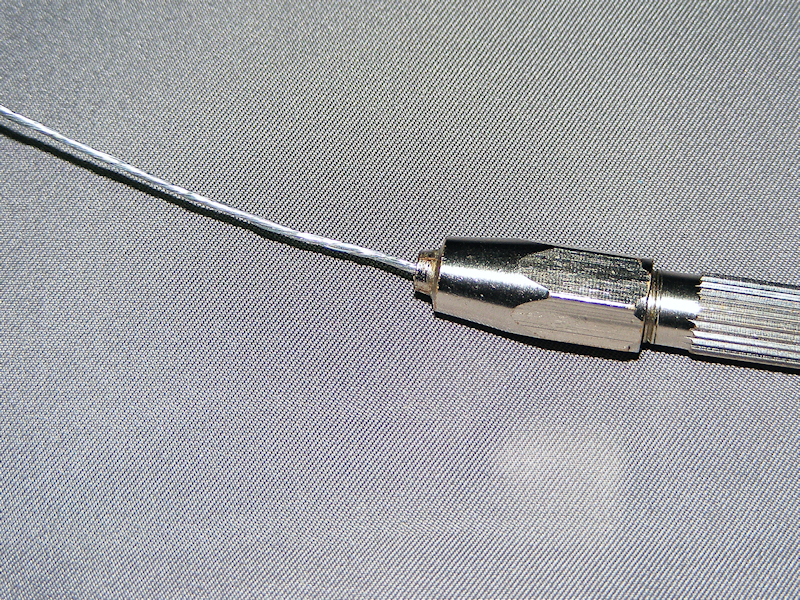
Using flat-nose pliers, I carefully flattened one end to create a strap-like appearance, then cut a 20mm length. One end was glued to the engine sump, and the other tucked behind the starter motor, just like the real thing. A tiny drop of superglue at each end held it securely.
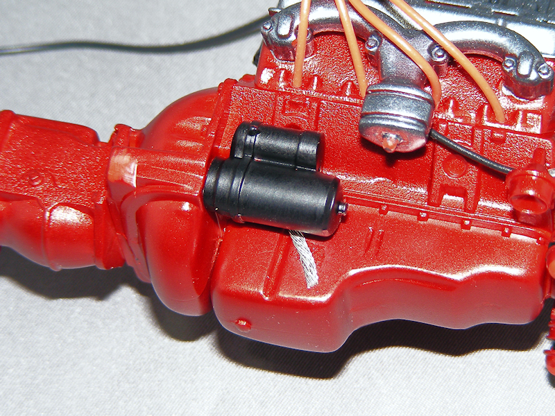
Why It Matters:
These details might seem minor, but they add a sense of mechanical credibility to the engine bay. Even if they’re not immediately obvious, they contribute to the overall impression of a carefully built model.
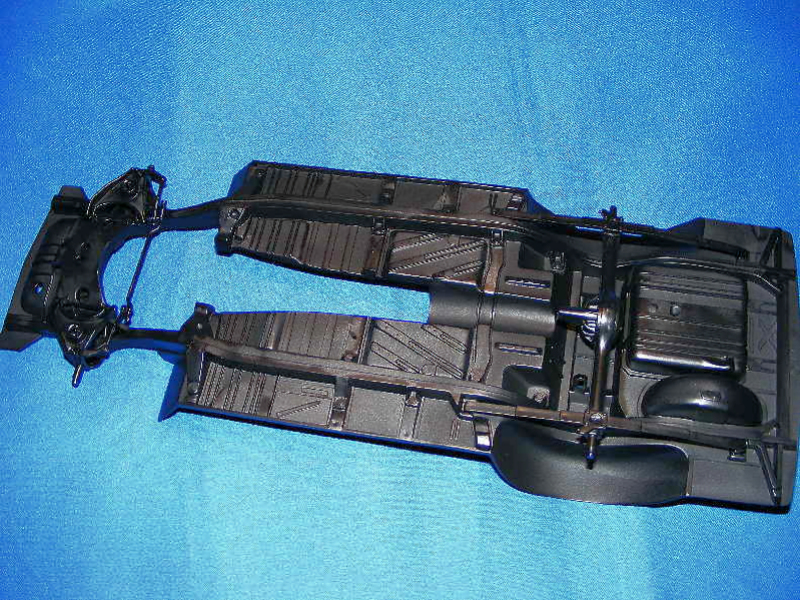
With the engine details wrapped up, I moved on to the chassis, which is a critical stage for any build, but especially for a strip car where stance and strength are everything.
Because I’m building the strip version with larger rear wheels, I started by gluing in the four extension blocks to the rear spring mountings. This modification raises the rear end and provides clearance for the oversized tires. The rear axle assembly itself needed a bit of work: I sanded away all seam lines, filled any gaps with putty, and then re-sanded for a smooth finish. Once satisfied, I mounted the axle onto the rear springs and set it aside to dry thoroughly.
The front suspension in this kit is a solid unit, which makes assembly straightforward but leaves little room for error. I glued the top suspension mounts in place, checking alignment carefully so the wheels would sit straight and true. These parts were left to cure before moving on.
Assembly Tips:
When fitting the rear axle assembly, I only glued it to the front two extension blocks at first. This left the rear slightly flexible, which is essential for getting the exhaust system in place later without forcing or distorting the chassis. Once the exhaust was installed, I could go back and secure the rear mounts fully.
With the main chassis assembled, I sprayed the entire unit with “Satin Black” primer for a clean, uniform base. To add visual interest and realism, I highlighted the rear leaf springs with “Oily Steel” paint, simulating the look of real steel springs under a working car.